Three Fatally Injured After Main Rotor Failed In Flight
The Canadian Transportation Safety Board (TSB) has released a report detailing an accident involving a Bell 206L helicopter which suffered an in-flight separation of its main rotor. All three occupants of the aircraft received fatal injuries when the helo impacted terrain.

According to the report, the aircraft had been chartered by a forestry company for a local timber survey flight to the south of Kapuskasing. Two passengers, employed by the forestry company, and 1 pilot were on board the aircraft. At approximately 1048 Eastern Daylight Time, about 15 nautical miles south of Kapuskasing, an in-flight separation of one of the helicopter’s main rotor blades occurred. As a result, the helicopter struck terrain and the helicopter was destroyed. There was no post-impact fire. The emergency locater transmitter activated upon impact, and a search and rescue team was deployed. The helicopter was located by a civilian helicopter prior to the team’s arrival.
The report indicates that the helicopter struck the ground at approximately a 40° nose-down angle and a 52° left-bank angle. The main rotor system, including the transmission, and the top of the fuselage separated as a unit in flight, prior to impact, and came to rest approximately 140 feet west of the main wreckage. The engine also separated from the airframe prior to impact and came to rest 170 feet north of the main wreckage. Various other components which separated in flight were strewn about the area.
Both main rotor blades remained attached to the hub. One blade was significantly damaged, but was not fractured. The other blade was fractured, and approximately 8 feet of the outboard end was missing. An extensive search was conducted for the remaining outboard section, but it was not located.
The pilot was wearing a safety belt and a two-point shoulder harness, as well as a flight helmet. Both passengers were wearing the lap portion of the safety belt. Although shoulder harnesses were available, they were not used by either passenger, nor was it required by regulation for aircraft in this category.
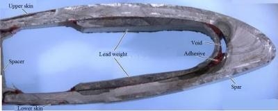
According to the report, the main rotor blades on the B206L are an all-metal bonded assembly consisting of 3 structural members: an aluminum spar, a spar closure, and a trailing edge strip. Skins, stabilized by a honeycomb core, are bonded to the major section by adhesive applied under heat and pressure. Reinforcing doublers, grip plates, and drag plates are bonded to the blade butt end. A lead weight runs along the length of the spar, beginning approximately at blade station 100, and continues for 115 inches to the blade tip. During the manufacturing process, the lead weight is attached to the spar with adhesive.
The fractured main rotor blade and the mating main rotor blade were sent to the Transportation Safety Board of Canada (TSB) Laboratory for further examination. The fractured blade (part number 206-015-001-115, serial number A-4705) exhibited a complete chord-wise fracture approximately 100 inches (8 feet 4 inches) from the tip, about at blade station 121. Visual examination of the occurrence blade revealed that the fracture that led to the blade separation had initiated in the blade leading edge spar. The fractures of the blade skin, spar spacer, trailing edge wedge, and aluminum honeycomb structure were all secondary due to overstress. No deficiencies were found with the blade spar material. The spar material was 2014-T6, with a Rockwell B hardness of 78 HRBW, as specified by the manufacturer.
The lead weight was bonded to the aluminum spar with adhesive. There was a large void in the adhesive at station 121 (location of fracture). The span-wise length of the void in the inboard direction from the fracture surface was about 13 inches. The total length of this void is unknown since the outboard portion of the blade was not recovered. The cross section of the void measured approximately 9.5 millimeters (mm) x 1.5 mm (0.374 x 0.0591 inches).
The blade spar fracture initiated on the inner surface of the spar, at the location of the void in the adhesive used to bond the lead weight to the spar at station 121. The fracture initiation location was a visible fingernail-shaped region, which is typical of fatigue cracking, and was clearly identifiable, even in the condition in which the blade was received. The fingernail-shaped region in the fracture initiation area had a different appearance than the rest of the fracture surface. This region appeared dark, which suggested a corrosion deposit on the surface. In addition, the fingernail-shaped region had a relatively flat and smooth surface, which is typical of stable crack growth. The fracture surface in this area was oxidized with corrosion scale.
On 31 August 2008, near Greensburg, Indiana, an in-flight separation of a main rotor blade occurred on a Bell 206L-1 helicopter (registration N37AE) operated by Air Evac EMS Inc., followed by a collision with terrain and a post-impact fire. The 3 occupants suffered fatal injuries. As a result of the August 2008 occurrence, Bell Helicopter developed Alert Service Bulletin (ASB) 206L-09-159, which came into effect in July 2009 and was followed by a revision in November 2009. The ASB affected 2542 main rotor blades, including the occurrence helicopter’s blades.
The ASB stated:
"...that a fatigue crack could occur if there was a combination of both residual stress in the spar and a larger than acceptable void in the adhesive applied between the blade’s internal lead inertia weight and the spar, between blade stations 100 and 145. If such a condition exists, a fatigue crack may be induced by the centrifugal force variation that occurs during the helicopter start/stop cycles."
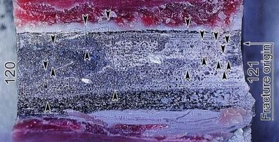
The investigation determined that micro-cracks in the adhesive material adjacent to the spar edge of the occurrence blade created a porous connection between the void and the interior cavity of the blade. Since the blades are not designed to be airtight, moisture likely penetrated through the cracks and inside the adhesive void, causing corrosion of the inner surface of the spar. Corrosion can accelerate fatigue and increase the crack propagation rate. Although no corrosion was observed in the previous accident, the overall fracture pattern was very similar to this occurrence. This suggests that, while corrosion could have been a facilitating factor, it was not the main cause of the fatigue fracture in the subject blade. The mating blade also had large adhesive voids, but there were no cracks in the adhesive, therefore no direct connection to the blade inner cavity, no corrosion in the void, and no fatigue cracks in the spar. The acceptable level of risk for critical components must be extremely
low.
An adequate inspection schedule of a critical component with a known manufacturing defect must provide an equivalent level of safety to the original certification standard. In this occurrence, the damage tolerance assessment proved inadequate, as the crack was not detected prior to separation.
The operator had performed the necessary wipe checks, but did not detect a crack.
(Images provided by the Canadian TSB. Top: Cross section of fracture rotor. Bottom: Spar inner surface with lead weight and adhesive removed, arrowheads showing secondary cracks)
 ANN's Daily Aero-Term (04.24.24): Runway Lead-in Light System